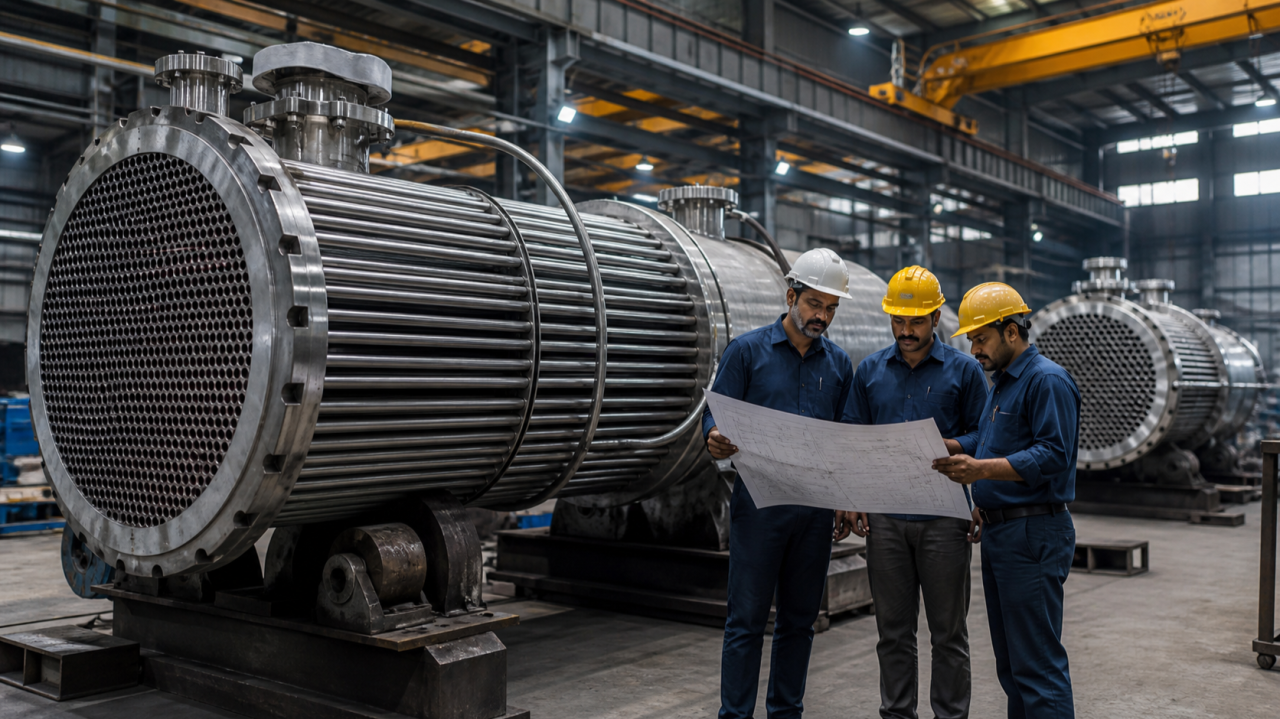
A heat exchanger is not selected by nozzle size and surface area alone. It must transfer the required heat under real process conditions while controlling pressure drop, corrosion, fouling, vibration, maintenance access and fabrication risk. A unit that performs on a clean design sheet may lose duty after deposits form or may become expensive to maintain because tubes cannot be cleaned or removed.
For process plants searching for a heat exchanger manufacturer in Chennai or India, a useful enquiry begins with a complete thermal and mechanical design basis. This guide explains the decisions that help owners, consultants and procurement teams compare shell-and-tube proposals and evaluate fabrication quality.
Quick answer: Define process duty and operating cases; confirm fluid properties and allowable pressure drop; choose the exchanger configuration for temperature programme, fouling and maintenance; select materials through corrosion review; evaluate vibration and thermal expansion; specify applicable codes, inspection and testing; and compare guarantees and documentation on the same basis.
1. Establish the thermal design basis
Provide inlet and required outlet temperatures, flow rates, compositions, phase changes, operating pressure, physical properties and fouling tendencies for both streams. Identify normal, minimum, maximum, startup, shutdown and upset cases. If the process involves condensation, boiling or variable composition, include the relevant range.
State allowable pressure drop separately for shell and tube sides. Excess pressure drop can increase pumping energy or disturb the process. Very low velocity can increase fouling. Thermal design is therefore an optimisation, not simply a surface-area calculation.
2. Decide whether shell-and-tube is appropriate
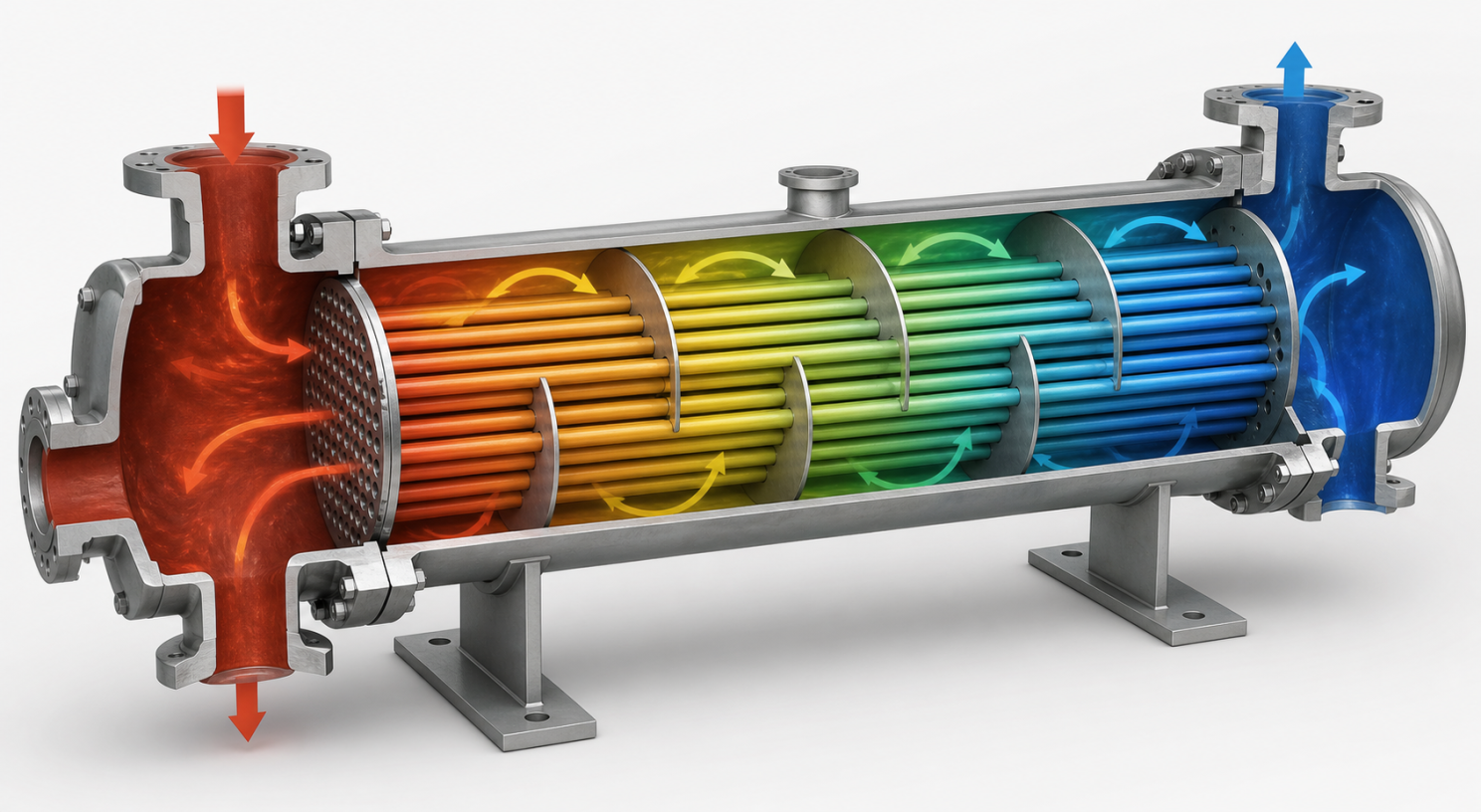
Shell-and-tube exchangers are widely used for demanding pressure, temperature, dirty service and maintainability. Plate, air-cooled, double-pipe or other designs may be better in different duties. The process designer should compare footprint, approach temperature, pressure, fouling, gasket compatibility, cleanability and lifecycle cost.
If shell-and-tube is selected, the configuration still matters: fixed tubesheet, U-tube, floating head, kettle reboiler and other arrangements manage thermal expansion and cleaning differently.
3. Select shell-side and tube-side allocation
Allocation depends on pressure, corrosion, fouling, viscosity, flow rate, allowable pressure drop and cleaning. High-pressure fluid may be placed inside tubes because the smaller diameter can contain pressure efficiently. A highly corrosive material may also be placed on the side where expensive alloy quantity can be reduced, subject to full design review.
Mechanical cleaning may favour putting a dirty service inside straight tubes. Viscous fluid may need shell-side geometry that promotes suitable velocity. There is no automatic rule; document the reasoning.
4. Manage fouling from the beginning
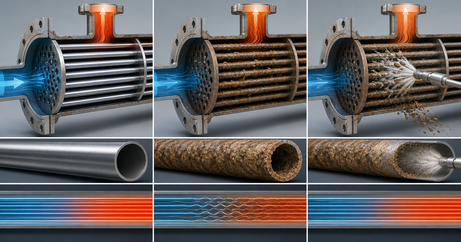
Fouling reduces heat transfer, narrows flow passages and increases pressure drop. Identify solids, scaling salts, polymerising compounds, biological growth, coke formation or corrosion products. Use realistic fouling factors and operating history rather than an arbitrary margin.
Design velocity, surface temperature, baffle arrangement and cleanability to limit deposits. Provide vents and drains. Plan chemical cleaning, hydrojetting, brushing or bundle removal as appropriate. A removable bundle has little value if the plant layout does not provide extraction space.
5. Choose materials through corrosion analysis
Review every process constituent, concentration, temperature, contaminants, oxygen exposure, cleaning chemicals and external environment. Carbon steel, stainless steels, copper alloys, nickel alloys and other materials have different strengths and failure modes. Cladding or overlays may be considered where technically justified.
Material compatibility applies to shell, tubes, tubesheets, channel, baffles, tie rods, gaskets, bolts and weld consumables. Dissimilar metals can create galvanic or fabrication concerns. Require material test certificates and traceability through cutting and assembly.
6. Address thermal expansion
Different shell and tube temperatures create differential expansion. A fixed-tubesheet exchanger can be economical but may develop high thermal stress unless expansion is accommodated. U-tube and floating-head designs provide flexibility with different cleaning and cost implications. An expansion joint may be possible but adds a component that needs careful design and inspection.
Consider transient conditions, not only steady-state temperatures. Rapid startup, steam admission or cooling can produce severe local stress.
7. Evaluate flow-induced vibration
Shell-side crossflow can excite tubes, leading to wear, noise or fatigue. Review unsupported span, baffle spacing, tube natural frequency, fluid density, velocity and two-phase behaviour. Nozzle impingement protection may be required.
Vibration analysis should be part of thermal-mechanical coordination. Reducing baffle spacing may support tubes but changes pressure drop and heat transfer. Procurement should ask how the vendor resolved this trade-off.
8. Define the governing codes and specifications
Specify applicable pressure-vessel code, project standards, statutory requirements, design life, corrosion allowance, wind or seismic loads, nozzle loads and client specifications. TEMA or other exchanger practices may define construction details and classes where contractually selected.
Code stamping, third-party inspection and regulatory approval are project-specific. The purchase order should state exactly what certification is required rather than assuming every workshop uses the same scope.
9. Review tubesheet and tube-joint design
Tubesheet thickness and ligament stresses depend on pressure, geometry, material and joint configuration. Tube-to-tubesheet joints may be expanded, strength welded, seal welded or combined according to service and specification. Joint quality affects leakage and repairability.
Require qualified procedures and representative mock-ups when the service or specification warrants them. Control tube-hole finish, cleanliness, expansion limits and weld inspection.
10. Design nozzles and supports for the plant
Nozzle orientation must match piping, venting, draining and maintenance. High inlet velocity may require an impingement plate or distributor. Check allowable nozzle loads and reinforcement. Provide thermowells, pressure taps and drains where process control needs them.
Saddles, lifting lugs, davits and bundle-pulling features should suit installation and maintenance. Confirm centreline elevation, foundation details, insulation clearance and shipping limitations before fabrication.
11. Build an inspection and test plan
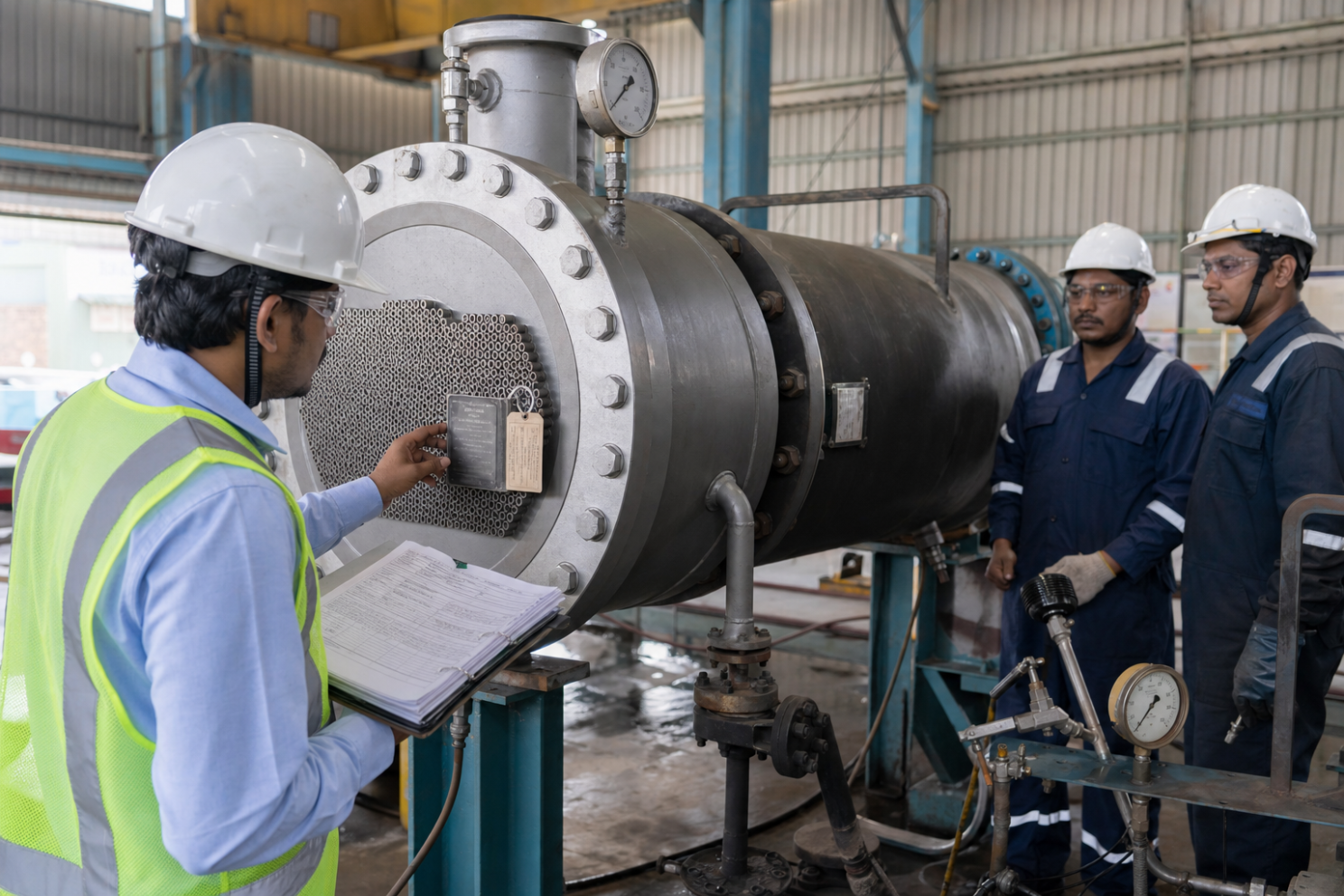
The ITP should identify hold, witness and review points for material receipt, identification, forming, welding, tube joints, dimensional checks, nondestructive examination, pressure testing, leak testing, painting and documentation. Acceptance standards and responsible parties should be stated.
Hydrostatic testing demonstrates pressure integrity under defined conditions but does not prove thermal performance or eliminate every weld defect. Pneumatic tests carry greater stored-energy risk and require rigorous procedures when justified. Special leak testing may be needed for hazardous or cross-contamination-sensitive services.
12. Verify cleanliness and preservation
Process service may require limits on oil, chloride, rust, dust or foreign material. Specify cleaning, drying and inspection. Stainless steel surfaces need protection from carbon-steel contamination. Cap nozzles, preserve machined faces and secure internals for transport.
Storage duration and site conditions should guide desiccants, nitrogen preservation or coating. Delivery is not the end of quality if the unit waits outdoors before installation.
13. Require useful handover documentation
• Approved data sheets, calculations and drawings
• Material certificates and traceability records
• Welding procedures, qualifications and welder records
• NDE reports, heat-treatment charts and test certificates
• Dimensional and tube-joint records
• Painting, cleaning and preservation reports
• Nameplate data and statutory certificates
• Operation, maintenance and recommended-spares information
Review the manufacturing data record progressively. Waiting until dispatch to discover missing traceability can delay the project.
How to compare heat-exchanger quotations
Normalise the thermal duty, fouling factors, pressure drops, materials, corrosion allowance, code scope, exchanger type, inspection, testing, documentation, delivery and exclusions. Compare guaranteed performance and remedy if the unit fails the agreed duty. Review lifecycle factors such as cleaning access, gasket and tube replacement, energy cost and downtime.
A lighter or cheaper design is not automatically inferior, and a heavier unit is not automatically better. The vendor should explain the engineering basis and deviations transparently.
Factory capability questions for a Chennai heat-exchanger vendor
Ask which comparable exchangers the workshop has completed, including material, pressure, size and service. Review engineering capability, drawing control, approved welding procedures, welder continuity, tube-expansion equipment, cranes, machining access, NDE coordination, pressure-test facilities and segregation for stainless or alloy work. Capacity should match the proposed delivery schedule, not only the vendor’s general brochure.
Walk the material route from receipt to dispatch. Check how heat numbers are transferred, cut parts identified, weld consumables stored and calibrated instruments controlled. Review nonconformance and repair records on a sample project. A transparent system is more valuable than a perfectly cleaned shop prepared only for the visit.
Commissioning and operating feedback
Before startup, confirm removal of transport restraints, cleanliness, correct gasket installation, venting, draining, insulation and instrument readiness. Warm up the exchanger at a controlled rate appropriate to the process. Record clean-condition temperatures, flows and pressure drops as a baseline.
Trend duty and pressure drop over time. When performance declines, compare operating data before assuming the exchanger is undersized. Flow changes, fouling, bypassing or control-valve behaviour may be responsible. Feed operating and maintenance experience back into the next specification so the organisation’s exchanger designs improve from project to project.
Frequently asked questions
What causes a heat exchanger to lose performance?
Common causes include fouling, reduced flow, air or vapour binding, bypassing, changed fluid properties, damaged internals and incorrect operating conditions.
Which side should a fouling fluid use?
Often the side that provides suitable velocity and easier cleaning, but pressure, corrosion, phase and thermal design must also be considered.
Is hydrotesting enough for acceptance?
No. It verifies pressure integrity under the test conditions. Material, welding, NDE, dimensions, cleanliness and thermal guarantees require separate evidence.
When is a removable bundle useful?
When the service benefits from external bundle cleaning or inspection and the plant provides enough extraction access and lifting arrangement.
Select the exchanger as a lifecycle asset
A heat exchanger succeeds when thermal duty, mechanical integrity and maintainability are solved together. A complete enquiry and disciplined vendor review reduce changes, fouling surprises and maintenance constraints.
GI Equipments designs and fabricates heat exchangers, pressure vessels, tanks, reactors, skids, filters and stainless-steel process equipment in Ambattur, Chennai. Project teams can engage early to align data sheets, drawings, materials, fabrication, inspection and documentation with the required service.