
Before releasing an industrial skid for fabrication, agree how the equipment and connected pipework will move, where loads will go, and who will approve the interface. A connection can match perfectly on a cold drawing and still experience unacceptable forces when the plant heats up.
For project engineers, plant teams and equipment buyers, the practical starting point is an interface review covering operating conditions, nozzle loads, support behaviour and the actual installation location. This guide explains the questions to resolve before fabrication. Final analysis, support design and acceptance must be completed by competent engineers using the applicable project requirements and equipment manufacturer's limits.
Why thermal movement belongs in the layout discussion
Hot pipework expands. The amount and direction of movement depend on its material, temperature change, length, routing and restraints. Connected equipment can also move, so the relevant question is how the two systems move relative to each other.
Spirax Sarco's pipe expansion and support guidance explains that piping needs both support and sufficient flexibility to accommodate operating movement. That principle makes thermal expansion a layout issue from the beginning, rather than something to address after the connecting spool arrives.
A compact skid may look attractive because the pipe runs are short and the package fits neatly into the available footprint. The useful design question is whether that arrangement also leaves a workable path for movement and access. Space saved in the layout can introduce constraints elsewhere.
For an early review, place the cold installation position, expected operating movement and required access space on the same drawing. This gives the piping designer, equipment designer and site team a shared problem to solve before each discipline commits to its own arrangement.
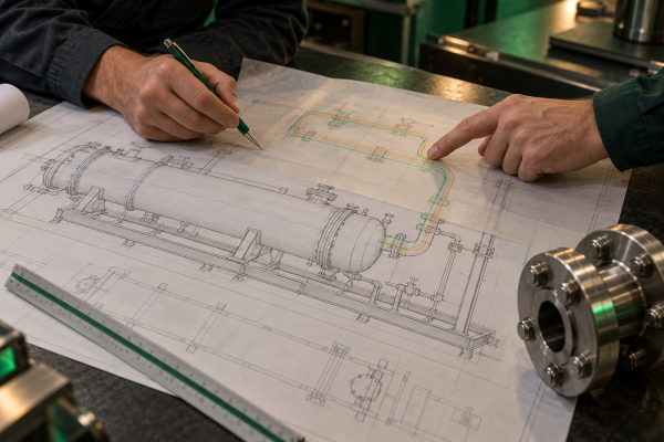
What nozzle loads actually describe
An equipment nozzle is the connection through which the process stream enters or leaves. Attached piping can transmit forces and bending or torsional moments into that connection. Pipe and fluid weight, thermal displacement and other applicable loading conditions all need consideration within the engineering design.
A pressure rating alone does not tell the project team what external piping loads a connection can accept. Likewise, a pipe-stress result needs to be assessed against the correct equipment interface criteria. Treat the piping calculation and equipment acceptance as connected reviews with named owners.
For example, the Spirax Sarco U-tube heat exchanger manual discusses calculating unavoidable pipe loads with their directions and obtaining manufacturer support where necessary. The relevance is the review process; its product-specific instructions should not be transferred automatically to another manufacturer's equipment.
Ask the equipment designer how allowable loads will be supplied and checked. Confirm the coordinate system, sign convention, units and assessment point. A set of numbers is not a usable interface if one party reports loads at a flange face while another assumes a different reference location.
Avoid an incomplete acceptance statement
“Loads acceptable” is too vague for a design review. Record which drawing revision, loading cases and nozzle arrangement were reviewed. If the piping route or support arrangement changes later, the earlier acceptance may need to be revisited.
This is particularly important when site piping is designed separately from the skid. The package supplier may understand the equipment very well while having limited visibility of the long pipe run outside the package boundary.
Start with the temperature story
Give the design team more than one normal operating temperature. Prepare a short account of how the system behaves across its intended operating cycle.
Include, where relevant:
- The ambient conditions during installation
- Normal and maximum operating conditions for each connected stream
- Startup, shutdown and standby conditions
- Cleaning, steaming or regeneration conditions
- The expected frequency of operating cycles
- Situations in which adjacent lines or equipment are at different temperatures
Do not combine unrelated extremes into a supposedly conservative case without engineering review. Some conditions occur together; others do not. The analysis owner should define meaningful combinations and document the assumptions.
A useful review question is: “Which operating state is most likely to be missed if we look only at the normal process datasheet?” It invites operations staff to contribute information that may be absent from a steady-state drawing, such as intermittent hot cleaning or an idle neighbouring circuit.
Give every support a clear job
Supports can carry weight, restrain movement or guide it in intended directions. These functions need to be distinguished. An extra restraint added for convenience can change the way a pipe system responds to temperature.
An anchor establishes a restrained point in the designed arrangement. A guide controls specified movement while allowing movement in other directions. A sliding support carries load while permitting intended sliding. The detailed constraints and friction assumptions are engineering inputs, not decisions to improvise during installation.
At the interface meeting, ask the following:
- Which supports belong to the skid and which belong to the site?
- Which structural members receive their reactions?
- Who provides the support design and who verifies the supporting structure?
- Which movements are intended, and what clearances do they require?
- Are temporary transport restraints clearly distinguished from operating supports?
The value of these questions is ownership. A support drawn just outside a vendor's package boundary can otherwise remain an assumption on both sides of the contract.

Review the connection and the surrounding space together
Nozzle orientation affects more than whether two flanges meet. It influences the space available for the pipe route, adjacent valves, insulation, instruments and service access.
Use a coordinated drawing review to check the real site context. Confirm the equipment datum, nozzle centreline, orientation and the site tie-in location. Include realistic space for insulation and intended movement, without treating an unverified clearance as an approved design value.
The Graham plate heat exchanger manual explicitly addresses the need to avoid harmful nozzle loading from connected piping weight and thermal expansion, and requires approval of applied forces and moments for its equipment. It illustrates why connection design requires more than dimensional fit.
For project coordination, keep three views separate enough to understand but close enough to compare: the position at installation, the movement envelope in service, and the space required for planned equipment access. A clash in any one view deserves resolution before fabrication release.

Check the quality of site information
Record whether each tie-in dimension comes from a verified survey, an existing drawing or an assumption. An old drawing may be useful background without being sufficient fabrication input.
If a critical location remains uncertain, identify the measurement or decision required and the person responsible. Avoid hiding uncertainty inside a precise-looking dimension. A clearly marked open item is easier to manage than a confident number that later proves wrong.
Expansion joints need a system-level decision
An expansion joint may be appropriate, but its suitability depends on the system around it. The Expansion Joint Manufacturers Association describes flexibility as something engineered into the overall piping design.
Different joint arrangements accommodate different movements. Pressure thrust, restraint arrangements, stability and movement limits require specialist consideration. EJMA's bellows guidance also explains that tie rods and limit rods have different functions and that torsional loading is a concern.
For the project team, the useful action is to ask for a complete proposal: the selected joint arrangement, required anchors and guides, structural reactions, movement basis and inspection needs. A component quotation without those interface requirements leaves important decisions unresolved.
Do not specify a flexible connection merely to absorb a site misalignment. Refer discrepancies to the responsible engineers. This article is a planning guide and does not provide instructions for modifying restraints or correcting installed pipework.
Use a short interface register
A practical interface register can sit alongside the general arrangement drawing. Give each critical connection a row and keep the information concise enough to review in a meeting.
For each connection, record:
- Equipment and nozzle identification
- Current drawing revision and site datum
- Piping designer and equipment approval owner
- Applicable operating cases and movement information
- Load submission and acceptance status
- Support ownership on both sides of the boundary
- Site survey status and unresolved questions
- The change that would trigger a repeat review
The register should point to the engineering evidence rather than trying to reproduce the whole calculation. Its purpose is to show whether the interface is ready for release and what remains open.
This approach is especially useful when purchase, fabrication and site work run on different schedules. A procurement milestone may be complete while a site interface remains undecided. Keeping those statuses visible avoids confusing commercial progress with technical closure.
Hypothetical case study: a cooler beside an existing pipe rack
Consider a hypothetical factory installing a skid-mounted cooler near an existing pipe rack. The preliminary layout shows a short, direct connection from the rack to the cooler. The skid fits the nominated footprint, and the nozzle size matches the line specification.
During the interface review, the team discovers that the existing rack drawing does not identify the operating movement at the tie-in. The proposed site support also appears on neither supplier's scope. A maintenance access route overlaps the space being reserved for the connecting pipe.
The team records these as three separate issues. The piping engineer establishes the relevant movement and loading cases. The structural and package teams agree who owns the support and its reactions. The layout is reviewed with operations to preserve access.
Only after the resulting arrangement and nozzle loads are accepted does the team release the affected fabrication details. If the evidence points to a different route or support arrangement, that revision is made through the normal design process.
This is an illustrative planning scenario, not a GI Equipments customer case or a claim of measured savings. Its lesson is that dimensional compatibility can be established before the installation interface is actually ready.
Decide what a late change reopens
A moved valve, a revised nozzle orientation or a relocated support can affect earlier assumptions. Agree in advance which changes require the piping and equipment reviewers to reassess the interface.
Ask anyone proposing a change to identify the affected connection and drawing revision. The technical owner can then determine the necessary review, rather than relying on the apparent size of the modification.
ASME's B31.3 Process Piping overview describes a broad code scope covering process piping. The applicable code, edition and project requirements must be selected by the responsible engineering team. A general online guide cannot establish compliance for a particular skid.
Frequently asked questions
Can a successful shop pressure test prove the site interface is acceptable?
It does not establish every operating load imposed by the final site piping arrangement. Review the interface using the agreed conditions and manufacturer criteria, alongside the applicable fabrication and testing requirements.
Is a longer pipe route always better for thermal movement?
No. Routing, restraints, weight, process requirements and available space interact. The engineering team must assess the proposed arrangement; length alone is not an acceptance rule.
Should every skid include expansion joints?
No universal rule applies. The responsible designer should assess the available flexibility and choose an appropriate arrangement, including the associated restraint and support requirements.
What should a buyer send before the first interface meeting?
Send the process basis, preliminary layout, equipment connections, available site information and known operating cycles. Identify assumptions clearly and ask who owns piping analysis, equipment acceptance and site support design.
Bring the interfaces into the fabrication conversation early
GI Equipments lists process skids, heat exchangers and other fabricated process equipment in its portfolio. For a new enquiry, include the installation context alongside the equipment duty so that the technical discussion can address the connection to the wider plant.
Before approving fabrication, ask one final question: “Can each responsible party explain how this connection fits, moves and transfers load in the agreed operating conditions?” A clear, evidenced answer is a stronger starting point for installation.
Sources and technical references